Category Archives: Audio/Electronics Theory

127th AES Convention

AES127So it’s been a while since I’ve had a chance to post here, but I just got back from a weekend of AES and I need to report on the happenings.

I made it down Thursday night and stayed until the end of the program on Monday: four long days at the convention and a great time catching up with friends both living in New York and visiting for the show.

If you haven’t been to an AES convention, they’re broken up into two distinct parts: a trade show, with equipment designers and manufacturers showing off their new products, and a technical session, where industry professionals and research can share their recent work.  Usually you can cover the trade show in a day, though this year it took a lot less time.  Through some combination of the economy and industry politics many manufacturers did not attend; I think the most conspicuous absence was Digidesign, since they usually have a huge booth with half hourly product demos.  For me the highlights here included the Shure booth, where I got to check out their new ribbon mics and visit with old colleagues, and the Grace Design booth, where they were showing off their new 500-series preamps.

The technical program was a little quieter than usually, but much more lively than the exhibit floor.  Some of my personal highlights were the Max for Live presentation, the Headphone and Earphone Measurement Tutorial, David Berner’s presentation on emulation of analog hardware in DSP, and a number of papers I had a chance to catch.

I’m planning to write a bit about some of the presentations I saw, so stay posted.  Also, hopefully this will be the beginning of a more regular posting schedule.
Creation ADC

creation_adc_500

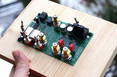
The Altmann Creation ADC is a converter that contains ‘No Analog or Digital Filters.’  This is a really interesting claim.  Non-ideal brickwall filters will introduce some phase shift, but the consequences of not implementing the filters at all seems much, much worse.  Any content above the sample rate will alias down, creating a tones that are not harmonically related to the original signal.

Altmann Creation ADC

Turn Me Up!

Turn_Me_Up_Logo_SmallSimilar to the the Pleasurize Music! project I mentioned a while, turnmeup.org is a website dedicated to increasing the dynamic range of new albums.  Their goals are stated as: 1) Defining an objective measure of dynamic range on a record, 2) defining a level of dynamics that is considerably more dynamic than today’s agressively limited records, but not so quiet that it wouldn’t be an option for contemporary artists, and 3) establishing and putting into place a system to measure and certify records that would like to be considered for Turn Me Up! certification.

They’re letting people join the organization as supporters, submit albums to be certified, and become mastering houses capable or certifying records.  This looks like an interesting project, and Vagrant Records (among others) is one of their corporate sponsors; I just hope this all leads somewhere!

SMH-CD

Previously I wrote a little about the Blu-Spec CD - a red book CD burnt with a shorter wavelength blue laser.  In theory, the digital signal on the Blu-Spec CD should be less prone to errors in playback.

The SMH-CD is a very similar idea: a red book compatible CD created through a new process to reduce errors on playback.  In the case of the SMH-CD (Super High Material CD), the base material is a special polycarbonate plastic designed to increase the transparency on the data side of the disc.  The increased transparency means less distortion on the signSMH-CDal read by the laser, and a more accurate playback.

I can’t find any SMH-CDs for sale, and there’s very little information about them on the internet.  It looks like Prince’s catalog was reissued in Japan at some point in this format, and there’s substantial debate about the sound quality of the manufacturing process.  If you know anything else about this format, toss it in the comments!

Clarity Track by Track

Clarity Live

Clarity Live

One of my favorite records, by far, is Jimmy Eat World’s Clarity.  I know every note, from the organ and snare drum opening of Table for Glasses to the last loop in the perfectly evolved Goodbye Sky Harbor.  I was able to get tickets to see them on the Clarity X10 tour at the House of Blues in Boston, and I’m glad they’re releasing a live album from the tour.

I was poking around on their website the other day and fell into a gem: a track-by-track set of notes and comments by Jim Adkins (guitars, vocals) and Zach Lind (drums).  Among the highlights are the inspiration from Low for the opening, the drum machine magic in 12.23.95, and the epic drum production of Goodbye Sky Harbor (two tape loops, one speeding and one slowing!).

Clarity Track by Track

Journal of the AES - May 2009

The May AES Journal just dropped, and there are a few articles that look intriguing.  The first is a measure of objective speech intelligibility that will work with perceptual coding algorithms - definitely something needed since STI fails with perceptual coders.  They recommend some amendments to the ITU standard to handle the perceptual encoders.

There’s an article discussing the optimum bandwidth for AM and FM broadcasting.  For speech and classical music listeners preferred lower bandwidths of 5-7KHz - it seems that the lower bandwidth reduces noise from nearby channels.  For listening to ‘highly compressed’ music, like rock, most listeners could not tell the difference between 7 KHz of bandwidth and 10 KHz of bandwidth… interesting.  I’ve been observing the same thing recently: many people just don’t pay attention to the content above 8 KHz.  It’s a shame - I think that’s my favorite part.

For loudspeaker designers there’s an article about the impact of heating in the voice coil of speakers, and the impact it has on sound level and damping.  The result, as expected, is compression of the output, but the frequency response was also impacted by the damping changes.

Journal of the AES - May 2009

The 127th AES Convention is going down October 9-12, 2009, back in Javits Convention Center in NY!

Pleasurize Music!

Pleasure Music Foundation Dynamic Range Meter

Pleasure Music Foundation Dynamic Range Meter

Peter Kirn at Create Digital Music did a post on the Pleasure Music Foundation back in March.  The Foundation aims to put the pleasure back in music - pleasurize music! - by advocating for greater dynamic range in music.  From their Aim:

<

p style=”padding-left:30px;”>Our aim is to improve the sound quality of music in its various recorded formats – including data compression methods such as MP3 – as well as music destined for radio broadcast. Only music that provides a positive musical listening experience has real market value. The Foundation’s aim is to increase the value of music within the creative production process for the entire music industry. The objective is to revive the willingness to pay for music and therefore to create a healthier basis for all creative participants within the music industry.

They’ve produced a Dynamic Range Meter that gives every recording a score, a function of the peak amplitude and rms level (though this is really the crest factor of the music, not the dynamic range).  The meter is available for all platforms.

+4 dBu / -10 dBV

+4 dBu / -10 dBV:  These values are typically used to represent ‘Pro’ and ‘Consumer’ audio signal levels - some gear even has a switch to scale the output, or to adjust input gain.  So what do these values mean on a common scale?

First we need to know how to get from dB to volts.  For linear measures like volts, we defined the measure in dB to be 20log10(volts/reference).  To go backwards we’ll need volts = reference10^(dB/20).

You’ll recall from a previous post that the reference for dBV is 1 volt, and the reference for dBu is 0.775 volts.

Let’s convert 4dBu to dBV, via volts:

0.775*10^(4/20) = 1.228V

20*log10(1.228/1) = 1.8dBV

So +4dBu=+1.8dBV, and the difference between +4dBu and -10dBV is really about 12 dB.

dBV, dBu, and dBm

I’ve always have a little trouble remembering the relationship between dBm and the more common signal measurements of dBu and dBV.  The other day I was looking at a transfer function, and I was given results in dBm - the impetus for this post.

First, I should make sure we’re all on the same page.  What is a decibel (dB)?  The decibel is a relative measurement.  For voltage we calculate dB as 20log10(Voltage/Reference), where the reference can be absolute (like with dBu and dBV) or relative (plain old dB).  For an amplifier that outputs a signal twice as large as the input, 20log10(2/1) = 6 .02 dB.  If we ran a signal through this amplifier twice, our output is 4 times as large as the input, or 20log10(4/1) = 12.04dB.  This is the value of a dB scale - we can add gain values in dB instead of multiplying them: 22=4, while 6.02+6.02=12.04.

Before going on I should point out that dBm is not an appropriate measure for a transfer function.  Straight dB is the way to go, as a linear transfer function should produce an output relative to the input - not relative to an absolute value like dBm, dBu, or dBV.  Let’s say I put 0.5 volts into a system, and I get 0.25 volts back out: 20*log10(0.25/0.5) = -6 dB.

So then dBV, dBu, and dBm are all absolute measurements and each has a defined reference value:

  • dBV - 1 Volt
  • dBu - 0.775 Volts
  • dBm - 1 Milliwatt

dBV is straight ahead and simple to work with - this is the measure I use most frequently.  The dBV value of any voltage is 20*log10(V/1), so 1 Volt is 0 dBV, 2 Volts is 6 dBV, and 0.5 Volts is -6 dBV.

Let’s skip to dBm for a second.  This has a reference of 1 milliwatt, a unit of power.  Power is related to voltage by the equation P = VV/R, where R is the resistance the power is dissipated through.  For instance, if I drive 1 Volt into 1000 Ohms of resistance, 1V1V/1000Ohms = 0.001 Watts = 1 mW.  If I increase the voltage by 6 dB (a factor of 2) to 2 Volts, now I’m dissipating 2V2V/1000Ohms = 4 mW.  This is important - doubling the voltage does not lead to a doubling of power, since the power is related to the square of the voltage.  We actually have to use a different formula for dB of power, 10log10(Power/Reference).  With this formula, if we put in our 4mW and 1mW from above, we still get 6 dB of gain.  Math works!

Back to dBu.  dBu is referenced to 0.775 Volts - an odd number to use as a reference.  However, if you calculate the power dissipating by 0dBu through 600Ohms (a long-standing common value for transmission lines), you wind up with exactly 1mW of power, 0dBm.  So 0dBu = 0dBm, if and only if the load is 600 Ohms.  At any other load impedance this relationship changes.

So back to that transfer function in dBm.  In order to get a relative dB measurement I needed two things: the source voltage and the load impedance.  Knowing the load impedance allows you to calculate the voltage output from the system: V = sqrt(PR).  This is still an absolute measurement, so you need to know what the input signal was to calculate the dB out: 20log10(Output/Input).

SM57 Tape-Op Mod, Part II


Removing the transformer from an SM57

Removing the transformer from an SM57


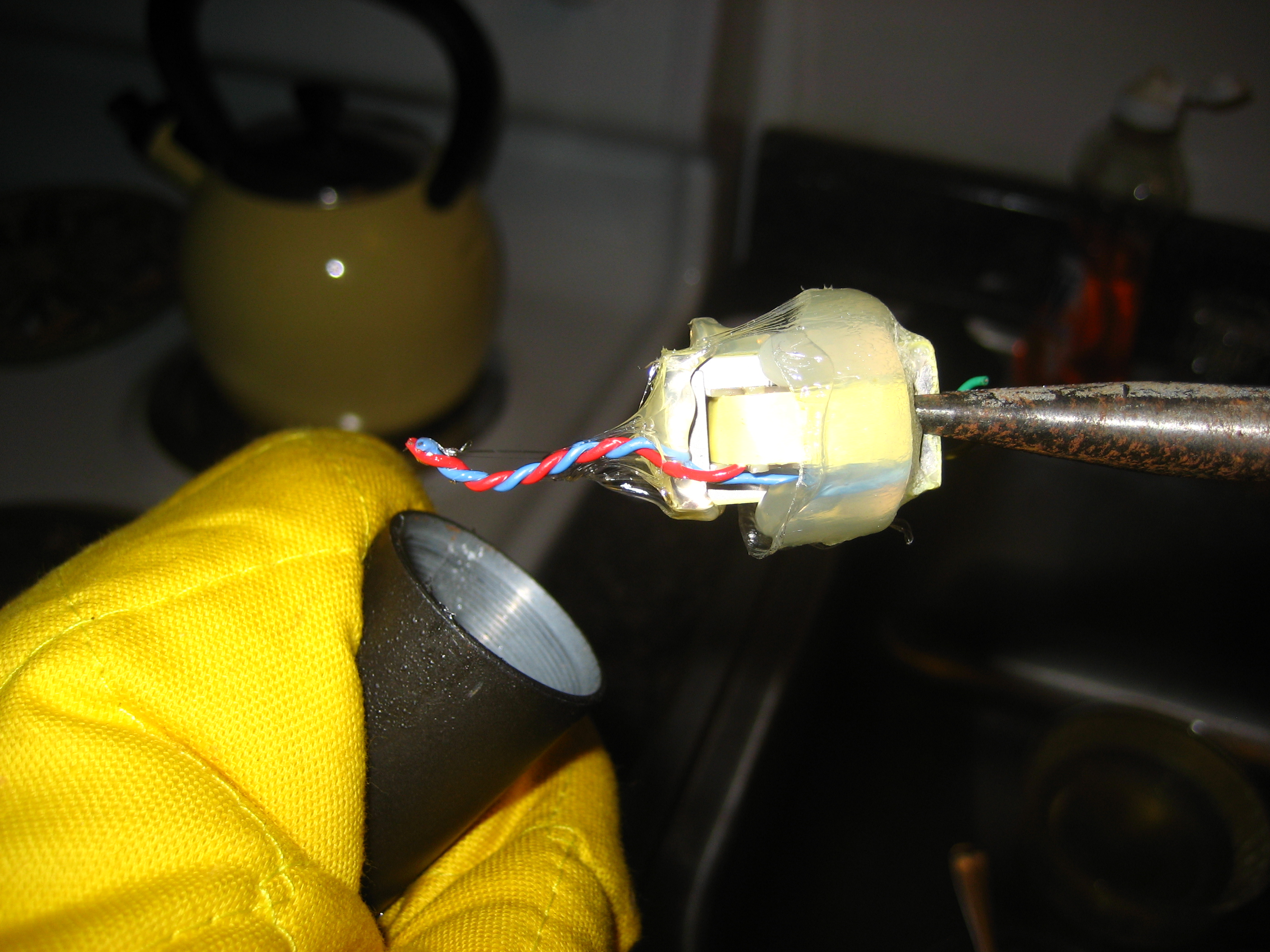
Tonight I got around to the destructive part of this mod.  I pulled the SM57 apart, which is pretty straightforward.  A small screwdriver to loosen the XLR connection, and then you can just unscrew the mic capsule from the body.  Cut the wires, and you’re ready to attack the transformer.

I put the body of the mic in a pot with a small amount of water - the water just covered the body while it was on its side.  I heated the water, and as it approached a boil, I picked up the mic body with needle nose pliers and an oven mitt.  Then I used the needle nose pliers to grab the transformer, and it slid right out of the mic.  Check the gallery to the right.

I cleaned up the glue from the transformer, in case I need or want to use it again.  If I don’t like the way this mod sounds, I could hot glue the mic back together (for better or worse).

The only comment I have on this step is the effect of the hot water on the exterior of the microphone - it seems to have really affected the finish.  It’s much rougher on this section of the microphone now than it is on the capsule end.

The only remaining step is to connect the mic capsule directly to the XLR jack and screw the body back together.  Pin 1 will still go to the body of the mic, and the blue and red wires will go to pins 2 and 3.  I’ll just have to try one arrangement, look at the polarity, and flip as needed.  I’ll post again once I’ve finished!