Tag Archives: circuits

Creation ADC

creation_adc_500

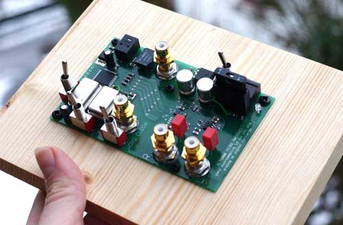
The Altmann Creation ADC is a converter that contains ‘No Analog or Digital Filters.’  This is a really interesting claim.  Non-ideal brickwall filters will introduce some phase shift, but the consequences of not implementing the filters at all seems much, much worse.  Any content above the sample rate will alias down, creating a tones that are not harmonically related to the original signal.

Altmann Creation ADC

+4 dBu / -10 dBV

+4 dBu / -10 dBV:  These values are typically used to represent ‘Pro’ and ‘Consumer’ audio signal levels - some gear even has a switch to scale the output, or to adjust input gain.  So what do these values mean on a common scale?

First we need to know how to get from dB to volts.  For linear measures like volts, we defined the measure in dB to be 20log10(volts/reference).  To go backwards we’ll need volts = reference10^(dB/20).

You’ll recall from a previous post that the reference for dBV is 1 volt, and the reference for dBu is 0.775 volts.

Let’s convert 4dBu to dBV, via volts:

0.775*10^(4/20) = 1.228V

20*log10(1.228/1) = 1.8dBV

So +4dBu=+1.8dBV, and the difference between +4dBu and -10dBV is really about 12 dB.

dBV, dBu, and dBm

I’ve always have a little trouble remembering the relationship between dBm and the more common signal measurements of dBu and dBV.  The other day I was looking at a transfer function, and I was given results in dBm - the impetus for this post.

First, I should make sure we’re all on the same page.  What is a decibel (dB)?  The decibel is a relative measurement.  For voltage we calculate dB as 20log10(Voltage/Reference), where the reference can be absolute (like with dBu and dBV) or relative (plain old dB).  For an amplifier that outputs a signal twice as large as the input, 20log10(2/1) = 6 .02 dB.  If we ran a signal through this amplifier twice, our output is 4 times as large as the input, or 20log10(4/1) = 12.04dB.  This is the value of a dB scale - we can add gain values in dB instead of multiplying them: 22=4, while 6.02+6.02=12.04.

Before going on I should point out that dBm is not an appropriate measure for a transfer function.  Straight dB is the way to go, as a linear transfer function should produce an output relative to the input - not relative to an absolute value like dBm, dBu, or dBV.  Let’s say I put 0.5 volts into a system, and I get 0.25 volts back out: 20*log10(0.25/0.5) = -6 dB.

So then dBV, dBu, and dBm are all absolute measurements and each has a defined reference value:

  • dBV - 1 Volt
  • dBu - 0.775 Volts
  • dBm - 1 Milliwatt

dBV is straight ahead and simple to work with - this is the measure I use most frequently.  The dBV value of any voltage is 20*log10(V/1), so 1 Volt is 0 dBV, 2 Volts is 6 dBV, and 0.5 Volts is -6 dBV.

Let’s skip to dBm for a second.  This has a reference of 1 milliwatt, a unit of power.  Power is related to voltage by the equation P = VV/R, where R is the resistance the power is dissipated through.  For instance, if I drive 1 Volt into 1000 Ohms of resistance, 1V1V/1000Ohms = 0.001 Watts = 1 mW.  If I increase the voltage by 6 dB (a factor of 2) to 2 Volts, now I’m dissipating 2V2V/1000Ohms = 4 mW.  This is important - doubling the voltage does not lead to a doubling of power, since the power is related to the square of the voltage.  We actually have to use a different formula for dB of power, 10log10(Power/Reference).  With this formula, if we put in our 4mW and 1mW from above, we still get 6 dB of gain.  Math works!

Back to dBu.  dBu is referenced to 0.775 Volts - an odd number to use as a reference.  However, if you calculate the power dissipating by 0dBu through 600Ohms (a long-standing common value for transmission lines), you wind up with exactly 1mW of power, 0dBm.  So 0dBu = 0dBm, if and only if the load is 600 Ohms.  At any other load impedance this relationship changes.

So back to that transfer function in dBm.  In order to get a relative dB measurement I needed two things: the source voltage and the load impedance.  Knowing the load impedance allows you to calculate the voltage output from the system: V = sqrt(PR).  This is still an absolute measurement, so you need to know what the input signal was to calculate the dB out: 20log10(Output/Input).
SM57 Tape-Op Mod, Part II


Removing the transformer from an SM57

Removing the transformer from an SM57


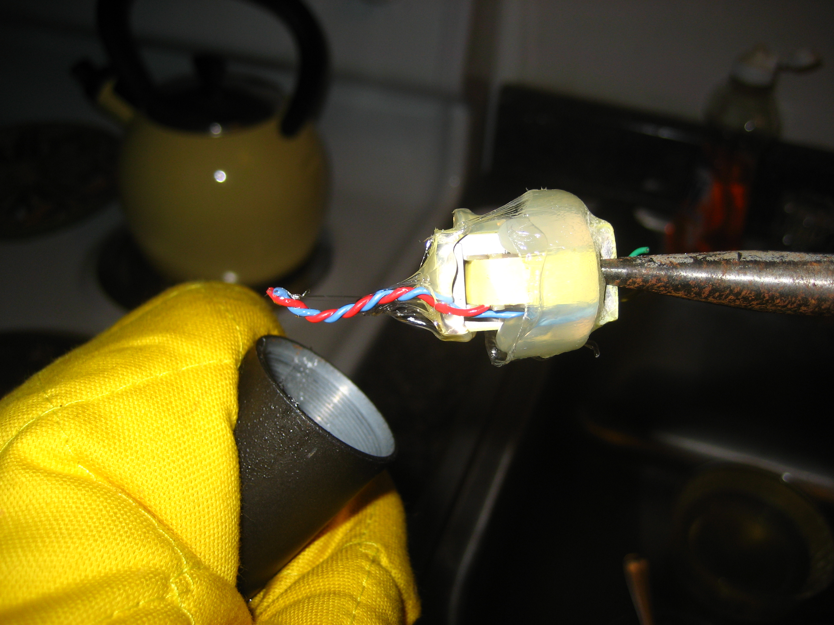
Tonight I got around to the destructive part of this mod.  I pulled the SM57 apart, which is pretty straightforward.  A small screwdriver to loosen the XLR connection, and then you can just unscrew the mic capsule from the body.  Cut the wires, and you’re ready to attack the transformer.

I put the body of the mic in a pot with a small amount of water - the water just covered the body while it was on its side.  I heated the water, and as it approached a boil, I picked up the mic body with needle nose pliers and an oven mitt.  Then I used the needle nose pliers to grab the transformer, and it slid right out of the mic.  Check the gallery to the right.

I cleaned up the glue from the transformer, in case I need or want to use it again.  If I don’t like the way this mod sounds, I could hot glue the mic back together (for better or worse).

The only comment I have on this step is the effect of the hot water on the exterior of the microphone - it seems to have really affected the finish.  It’s much rougher on this section of the microphone now than it is on the capsule end.

The only remaining step is to connect the mic capsule directly to the XLR jack and screw the body back together.  Pin 1 will still go to the body of the mic, and the blue and red wires will go to pins 2 and 3.  I’ll just have to try one arrangement, look at the polarity, and flip as needed.  I’ll post again once I’ve finished!

SM57 Tape-Op Mod - Plans

Back in the March/April 2006 edition of Tape Op, I saw an article about modding an SM57.  The premise is that the transformer adds a lot of unpleasantness to the sound.  The solution?  Remove the transformer!

Of course, the transformer is in there for a reason.  The two biggest reasons are to balance the output, and provide better voltage/impedance matching.  Removing the transformer will then unbalance the output (which could cause noise issues if you’re dealing with a significant cable run), and knock down the voltage output (by 10-20dB, reportedly).

With a small stack of 57s, it seems worth a try.  I’ll report back on my progress.


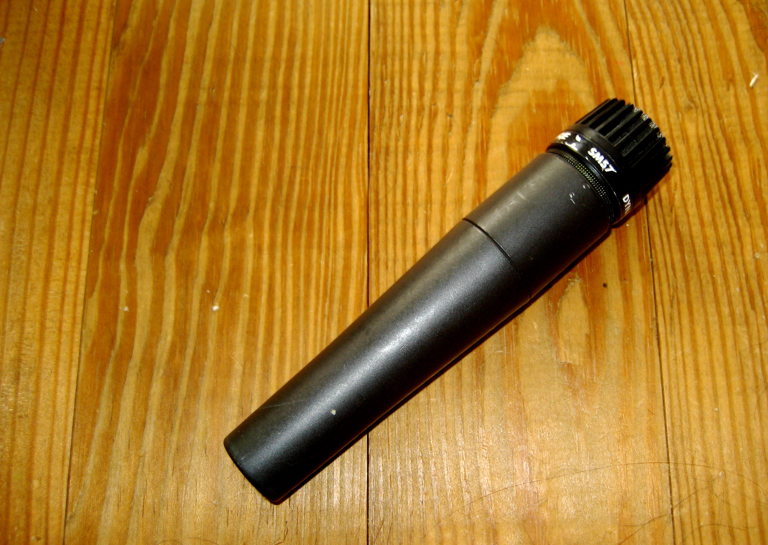
SM57 - Pre-Mod

SM57 - Pre-Mod


Links:

Tape Op - Best recording magazine available.

Gearslutz Forum #1 - Discussion of the mod outcome, plus pics.

Gearslutz Forum #2 - More discussion.

Catching Up: ProAud and the AES Journal

I spent the evening doing some reading - trying to manage the flood of ProAud discussion list emails I’ve received in the last few days, and browsing the latest AES Journal (Volume 56, Issue 12).  There are a few topics I want to dive into further, but there’s never enough time.  I imagine the list will continuing growing, but hopefully I’ll be able to dig into some of these topics over time:


Fractional Delay Filters (for delaying signals by non-integer multiples of the sample rate - useful in musical instrument modeling).  References to follow up on:

Principles of Fractional Delay Filters (Valimaki and Laakso)

Splitting the Unit Delay (Laakso et al.)

Efficient Algorithms and Structures for Fractional Delay Filtering Based on Lagrange Interpolation (Franck)


Grounding and shield termination - the work of Jim Brown, Bill Whitlock, and Henry Ott (among others).  References:

Journal of the AES Volume 43, Issue 6

AES Standards AES54-1, AES54-2, AES54-3

Noise Reduction Techniques in Electronic Systems (Henry Ott)


Listening Quality Tests.  References:

On Some Biases Encountered in Modern Audio Quality Listening Tests (Zieli’nski, Rumsey, Bech)

Are You Hearing What I’m Hearing? (Rumsey)


More to follow…